

More photos/videos here: https://photos.app.goo.gl/o8gtD6RszRP9zDCU9
There are several similar projects out there. I was inspired to do this for two reasons:
- A colleague of mine did it.
- I wanted to do something for the company IoT club
The wanting-to-do-something aspect also underlines these goals:
- it should be something easy-to-do
- (relatively) cheap
- captures the spirit of makers or creators
What you need
- Breadboards (3 x 400 pt board)
- Jumper wires
- Resistors. Anything >= 150 ohm and <= 300 Ohm - 7 Nos - all same.
- Wemos d1 mini
- USB cable/charger
- A PC (For writing code + flashing)
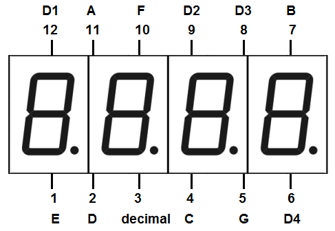
- 4-digit 7 segment display - 0.56 inch, common anode
- Hookup wires. U-shaped.
The 4-digit display can also come with a common cathode configuration. In this case, the wiring and coding will vary.
The wemos d1 mini is a wifi module board that has analog and gpio pins. It is mostly available with headers un-soldered. So its your responsibility to solder them.
For those uncomfortable with the soldering business, there is a version of this clock you can make with a similar module board - the nodemcu. It will be slightly different but, totally doable. There is a future plan to make one soon…
You probably can probably fit all this into a single 800 pt breadboard. And also do without the u-shaped hookup wires. I had slightly different objectives - “it should be a self-educational clock of sorts…” “should be wall mountable”…etc…etc…
Working principle

To display a number we need to do the following:
The only guiding principle you’d ever need - a LED should always have a resistor of suitable value in series.

Try to wire according to your convenience. Its not necessary to do it exactly as I have done it. Experiment with alternate placements and wiring. This will affect code.
As a general guide, study the various pinout of each module, make a note of what connects and where, and, then, arrive at the mapping. Then its only matter of editing the corresponding lines in code.
Create a new project in platformio. Select the Wemos D1 R1 and mini (wemos) for the board.
Next, copy/paste code from here: https://github.com/deostroll/breadboard-wifi-clock/tree/master/wemos-d1-mini/ntp-clock-2
- Where the digit (we want to display) should appear?
- In the appropriate digit location, what segments should appear.
- Ensure that only one segment lights up at a time
If you are tinkering, please connect a resistor to the segment pins (A to G) and 5V to anyone of the digit pins.If you try to show up a number such as “1” with these constraints you cannot manually do it. However, the wemos is capable of doing this very fast. The net effect of such blazing fast toggling of the LED segments is the illusion that, they are always on.
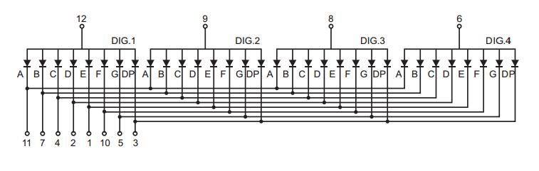
Wiring Diagram Guide

Breadboard wiring guide and mapping of pins.
As a general guide, study the various pinout of each module, make a note of what connects and where, and, then, arrive at the mapping. Then its only matter of editing the corresponding lines in code.
Editing and flashing code
Next, copy/paste code from here: https://github.com/deostroll/breadboard-wifi-clock/tree/master/wemos-d1-mini/ntp-clock-2
Files: main.cpp and platformio.ini
Assuming here that your pin mapping may be different.
After the breadboard wiring, make note of the connections between the display and wemos. Edit the code to reflect the pin mappings. To make job easier consider using the worksheet linked in code.
Once done, you need to update code to reflect your WiFi’s credentials.
For flashing code, you have to click on the Upload action: Click on the platformio icon, and find the action in the left sidebar.
This could take a few minutes.
That is it…
You should have a clock.
About the code assets shared
Other projects exist. This was me just thinking and experimenting other libraries and hacking.
Conclusion
So is this a good getting started project for learning about IoT?
TL;DR - NOPE. Just start with something. Take it slow. Know it is hard to find like-minded people. Be eager to experiment, learn, and, reach out.
The reason is simple. Most of the challenges involved in most personal projects simply go beyond arduinos or the esp8266, or the raspberry pi's, or, whatever (capable) devices (Smart devices, or, MCUs). The tutorials which you end up googling on the internet might cover specific areas which meet the primary objective. It cannot possibly cover everything...
And that is how tutorials should be - there is nothing wrong there!
Consider a washing machine at your house as an example.
How can a program/software sense that the washing machine is idle?
Most machines will sound a buzzer or an alarm. This is something our ears can notice. This is good, but not so much for software programs...Further, most products that are available on the consumer market are not specifically designed to interface to an external system such as a smart device or a computer. (The consumers today are mostly not IoT savvy 😏 ).
But, that mean, you have to always be there watching and listening to discern that specific state. You may want an alternate buzzer, probably installed in your living room, to make a sound to indicate that the washing machine is idle.
So making a remote buzzer make a sound is only one part of the whole challenge. You might use your smart devices to facilitate that. And in fact, one can say that you are doing IoT there to some degree...However, you haven't completed your project!
There is still the entire problem with actually sensing the idle state; how would you solve this?
Most arduino or rpi tutorials won't cover that bit to your satisfaction. But, if you look at it from this perspective - can we draw a silverline and assert that beyond that line you'd become an IoT expert?
Certainly NOT.
One cannot be an all-rounder in this field since it encompasses multiple disciplines and subjects. And with regards to this washing machine example - just leave a brief comment saying how YOU would solve it...
In the end, and if you are looking to get started with IoT, all I can say is, just start somewhere. Take up challenges - start small and gradually increase in complexity. The clock exercise is rather simple. It can get you started off. (Perhaps not this version, but stay tuned for the next version).
It is not easy to find like minded people here, but that shouldn't discourage you. Be open to experimenting, and, sharing your successes, and, failures. Join a club. Participate in forums. Maybe perhaps publish your version of a getting started project...
I hope you find this journey as fulfilling as your next...